

More news
- Focus on industrial: Powering the energy industry during extreme heat
- Focus on powder coatings: The coatings industry’s transition to PFAS/PTFE-free solut...
- “We see sustainability as a purpose, as a reason for doing business” – P...
- Focus on industrial: High-performance coating protects tanks at biopolymer production plan...
- Focus on powder coatings: Novel high-speed crosslinking technology
Ł. Maj, Z. Fogarassy, D. Wojtas, A. Jarzębska, F. Muhaffel, A. Sulyok, A. Góral, M. Kulczyk, H. Çimenoğlu & M. Bieda discuss their research on developing antibacterial coatings for medical use using in-situ silver nanoparticles in a micro-arc oxidation process during the processing of cp-Ti
Abstract
Silver nanoparticle (Ag-NP) containing antibacterial micro-arc oxidation (MAO) coatings have already been synthesised over titanium-based materials via the MAO process employed in silver acetate (AgC2H3O2) containing electrolyte. However, the way of incorporation and in-situ formation of Ag-NPs within the MAO coating have not been documented yet. Present work was initiated to reveal the mechanism of Ag-NP formation within the MAO coatings. Thus, the structure of the MAO coating fabricated on commercial purity titanium in the AgC2H3O2-containing electrolyte was investigated by electron microscopy techniques. To this end, the cross-sectional high-resolution electron microscopy studies were carried out on lamella cut out with the focused ion beam technique and these investigations were backed by X-ray photoelectron spectroscopy measurements of chemical composition on the surface of the MAO coating. These studies revealed that Ag is dispersed in the form of nanoparticles throughout the coating and that a higher density was confirmed closer to the micro-pores.
Introduction
Antibacterial surfaces are of high need as current estimates suggest that from 4 to 10% of patients receiving dental implants develop postoperative infections1. Bacterial colonisation and biofilm formation harm the substratum, where bacterial attachment can lead to implant failure along with inflammations of peri-implant tissues2. To reduce this risk, several attempts have been made to develop Ag-containing antibacterial coatings on Ti-based substrates, considering the antibacterial nature of Ag3,4,5,6. It has been stated that the fraction and size (i.e. surface-area-to-volume ratio) of the Ag particles play an important role in the antibacterial efficiency of coatings. In general, larger surface-area-to-volume ratios allow the substantial release of Ag+ ions to interact with the lipopolysaccharide molecules forming the outer membrane of the bacteria, disrupting its integrity and penetrating deep into the cell, damaging its DNA7,8. In this way, Ag affects the functioning of bacteria cells, resulting in the elimination or significant reduction of their activity. However, excessive release of Ag+ ions may lead to a cytotoxic effect on the tissues. It was confirmed that blood concentrations of Ag should not exceed 300ppb to prevent eventual side effects9. It has been reported that allowable Ag concentration in the plasma sprayed coating should be in the range of 2wt.%, which is regarded as the cytotoxic limit for coatings applied to metallic biomedical alloys, according to the reports in the literature10.
As the most promising surface modification technique for titanium implants, the micro-arc oxidation (MAO) process has the potential for fabricating thick, adherent and micro-porous titanium oxide coatings containing Ag-NPs, whose antibacterial characteristics could be adjusted by altering the concentration of the antibacterial agents in the electrolyte. Recently, a superior combination of bioactivity and antibacterial efficiency against Staphylococcus aureus has been obtained from the MAO coatings containing 1.14 and 0.7 wt% Ag for commercially pure titanium (cp-Ti) and Ti-6Al-4V alloy, respectively11,12.
In the literature, Ag-NPs-incorporated antibacterial MAO coatings were fabricated by adding Ag-NPs or Ag-containing chemicals/salts (silver acetate and silver nitrate) into the electrolyte. While Ag-containing salt-added electrolytes favour the formation of very fine Ag-NPs (~ 1–3 nm) within the MAO coatings, Ag-NP-added electrolytes tend to produce MAO coatings containing relatively larger Ag-NPs (approximately tens of nm13). When the size of the Ag-NPs is of concern, the addition of Ag-containing salt-added electrolytes tends to favour the formation of MAO coatings exhibiting more efficient antibacterial properties. Aydogan et al.11 reported that even such small addition of the AgC2H3O2 to the base electrolyte as 0.001 mol/l forms MAO coating having ~ 99.98% antibacterial efficiency against S. aureus after 24hr of incubation. Furthermore, Ag concentration in simulated body fluid was kept at levels below the cytotoxic limits for the human body, that is, 1.5 ppm after 14 days of the immersion12. Although studies showed that antibacterial MAO coatings produced with the addition of Ag-containing salts are more effective against bacteria than standalone NPs, the reason behind this (participation of Ag in the MAO coating in the form of NPs) remains unknown. Moreover, too little attention has been regarded to detailed microstructure studies aimed at explaining the way of Ag is incorporated from the AgC2H3O2 into the MAO coating.
Thus, within this work a detailed microstructural analysis, with particular attention on high resolution electron microscopy, was carried out in order to find the explanation of the very high antibacterial effectivity of MAO coatings having in-situ formed Ag-NPs produced with AgC2H3O2 presented in the report ‘Optimisation of micro-arc oxidation electrolyte for fabrication of antibacterial coating on titanium’11. In this study, electron microscopy observations were supported by surface-sensitive X-ray photoemission spectroscopy (XPS) analysis, often applied in efficient study of Ag-NPs, also for the TiO2-Ag system14,15,16,17,18,19. The results of the present study allowed to propose mechanisms of Ag-NPs formation from used salts and provide new insights into the fabrication of antibacterial coatings by a simple and cost-effective approach.
Materials and methods
In this work, titanium of commercial purity (grade 4) was used as a substrate material. The initial material, purchased from Wolften company in the form of a rod having a diameter of 50mm, was subjected to a plastic deformation covering multi-pass hydrostatic extrusion reducing its diameter down to 5mm. Details of this processing were described elsewhere20. The rod after hydrostatic extrusion was cut into cylinders of 4mm in height, ground with sandpapers and ultrasonically cleaned in ethanol and distilled water to remove the surface contamination before the MAO processing, aimed at fabrication of the coating.
Micro-arc oxidation of titanium substrates was performed in a stainless steel vessel filled with the electrolyte containing 0.1 M of Na2HPO4 and 0.002 M of AgC2H3O2 inorganic salts, dissolved in distilled water. The samples were immersed in this electrolyte throughout the process and alternating pulses of the positive and negative electric potentials of 300 and 60V, respectively, were applied to them using a bipolar pulsed power supply for an overall time of 5min. Each electric pulse was maintained for 0.6ms, separated by 0.4ms of breaks between them. The temperature of the process was kept at ~ 22°C.
Phase analysis of the produced coatings in macroscale was performed using the grazing incidence X-ray diffraction (GI-XRD) technique at an angle of 3° with a Bruker D8 Discover diffractometer equipped with a Co anode. Phase composition was achieved by indexing of the recorded spectrum (with a 2θ = 0.01° angular step and an acquisition time of 0.25 s per step) with the help of the DIFFRACplus software and the PDF4 crystallographic database. The crystallite size was evaluated by the analysis of the broadening of the peaks on the XRD spectrum using the Williamson–Hall (W–H) method performed in the HighScore Plus computer programme.
The SEM micro-scale observations of the coatings as well as the preparation of the lamellae for TEM studies were done using a ThermoFisher Scios 2 Dual Beam microscope, equipped with an EasyLift nanomanipulator for lift-out of the samples (FIB method). The TEM nanoscale microstructure observations were carried out with a ThermoFisher Themis G2 200 kV FEG microscope equipped with a ThermoFisher Ceta™ bottom camera, a Fischione HAADF/STEM detector and a ChemiSTEM™ energy dispersive X-ray spectrometer (EDS).
The chemical composition of the coatings was determined by the XPS method. X-rays from a water-cooled Al anode (providing 20 mA emission current using 15 keV excitation) irradiated the sample from an 18mm work distance and spectra were detected using a special retarding field cylindrical mirror analyser type DESA 150 (Staib Instruments Ltd, Germany). Spectra were recorded with a constant 1.5 eV energy resolution at 0.1 eV energy steps. The measurements were performed under an ultra-high vacuum of 1 × 10⁻⁹ mbar. The sample surface was cleaned to remove contamination before the XPS measurement through 30min of ion sputtering with an Ar+ ion beam using 1 keV energy, set to a glancing angle of 15°. To determine the peak intensities, the Gaussian/Lorentzian peak model function was fitted to the measured peaks involving the Shirley-type background subtraction. Additionally, concentration calculation took place assuming the homogeneous distribution model and using sensitivity factors from21.
Results and discussion
The SEM/BSE images presenting the MAO coatings with the addition of Ag are shown in Figure 1. They show that the whole surface is covered with the coating material with an average thickness of ~ 5 µm (Figure 1b). The MAO coating exhibits a high porosity with numerous micro-pores of diameters ranging from several tens of nm to several µm (Figure 1c). The images obtained at higher magnifications indicate the presence of a large number of fine spherical particles of high-atomic-number-elements that cover almost homogenously the whole coating surface (Figure 1d). It was observed that some of these particles protrude from the surface of the coating. The FIB lamella was cut out from the place shown in Figure 1c in a way to present the cross-section of the coating while avoiding larger porosity sections. SEM observations showed that the surface of the coating is free from larger agglomerates of particles, confirming that the MAO processing conditions were optimised efficiently. Additionally, indexing of the GI-XRD diffraction pattern revealed the presence of the anatase phase of the TiO2 with an average crystallite size of ~ 40 nm (Figure 1e). Furthermore, a weak signal from the substrate (α-Ti) was recorded. The lack of signal from the Ag in the GI-XRD pattern is explained by an insufficient signal-to-noise ratio, similar to the observation of Aydogan et al.11.
Figure 1
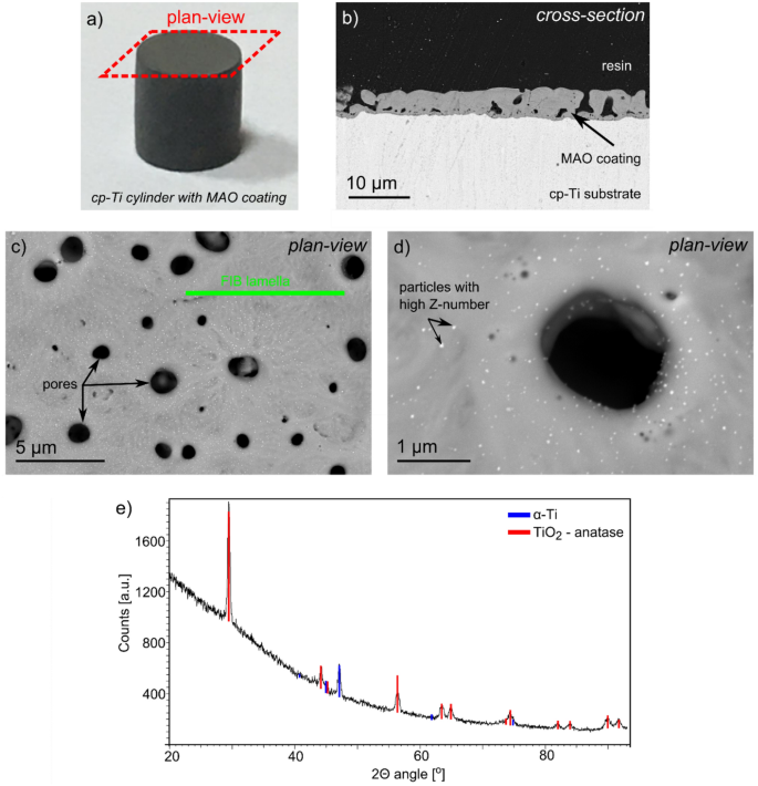
Macroscale photo of the cp-Ti sample with MAO coating (a), cross-section SEM/BSE image (b), plan-view SEM/BSE image of MAO coatings with the addition of Ag (c,d) and GI–XRD pattern recorded from the top surface of the MAO coating (e).
The TEM/BF images obtained from the coating cross-section showed the microstructure features typical for the MAO-coated samples (Figure 2). Presence of a thin continuous amorphous layer (up to 50nm in thickness) can be noticed at the coating/substrate interface, similar to the observations in20 securing a good bonding between them (Figure 2a). Above this, a porous zone consisting of a mixture of crystalline and amorphous oxides was formed. An almost fully amorphous zone (with only small crystalline inclusions) was visible farther from the substrate. The formation of amorphous zones can be attributed to a high cooling rate, which is up to 108 K/s due to very short micro-arc durations (mostly less than 1ms). On the other hand, the observations carried out at higher magnifications revealed the presence of fine spherical particles with a size < 10nm dispersed in the amorphous matrix (Figure 2b,c). These particles are non-uniformly distributed within the amorphous matrix: a much higher amount was located close to the pores than for the other areas of the coating. Only a small number of NPs has been observed in the areas far from the pores. The EDS maps of chemical composition presented in Figure 2d confirmed that the investigated particles are characterised by the increased signal of Ag with a simultaneous decrease in the number of counts from the other elements: Ti, O, Na, and P (dashed circles). This is an indicator that the Ag-NPs almost entirely aggregate within the amorphous phase, as confirmed by the SAED pattern presented as an inset of Figure 2c. Moreover, Figure 2c also shows the typical halo for amorphous phases, together with numerous spots of intensity originating from the crystalline Ag. The previous observation coincides with the studies carried out by Mosquera et al.22 that showed the addition of Ag tends to inhibit the amorphous-to-anatase transformation for the pulsed cathodic arc-deposited Ag-TiO2 coatings. In addition, our recent microstructure studies of MAO-fabricated TiO2 coatings obtained with Na2HPO4 electrolyte proved the formation of mostly amorphous transformation with a small contribution of the anatase phase residing mainly in the areas near the interface20.
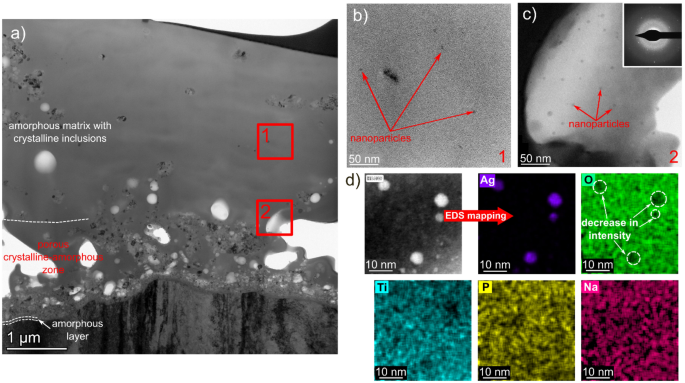
TEM/STEM images of MAO coating with Ag addition: BF images presenting a general overview of the coating (a), Ag-NPs in the central part of the coating (b), and agglomerates near the pores (c) as well as STEM/HAADF image showing Ag-NPs and accompanying EDS maps presenting distribution of Ag, O, Ti, P, and Na distribution (d).
The phase analysis of the NPs was performed based on the HREM images and indexing of the accompanying Fast Fourier Transform patterns (FFT) showed that they are of α-Ag (Figure 3a,b). In addition, the planar defects typical for Ag (twins) are also observed, which are the consequence of its low stacking fault energy23. The twins are represented by additional bright spots visible in the FFT image. Described results of a complementary approach covering the plan-view and the cross-sectional (on FIB lamellae) high-resolution electron microscopy studies show direct evidence of the nm-sized metallic Ag formation and its distribution in the titanium oxide-based coating during the MAO process. Despite the different studies made regarding the MAO process, few attempts have been made to investigate the way Ag incorporates into the coating from the AgC2H3O2 electrolyte during the MAO processing. Aydogan et al.12 confirmed by SEM observations that Ag-based particles agglomerate on the surface of the MAO samples were present, mainly in the surroundings of the micro-pores and craters. On the other hand, Wang et al.24 carried out the TEM study of the hydrothermally treated MAO coatings on the TiO2 pieces scratched off the surfaces. Although the presence of only one random Ag nanoparticle was shown, the distribution of the Ag-NPs and the way in which they embed into the coatings were elucidated.
Figure 3
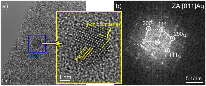
HREM image of single Ag nanoparticle oriented along [011] direction magnified in inset (a) and accompanying FFT (b) with reflexes from the matrix (M) and twins (T).
The XPS spectra acquired from the MAO coating produced with the electrolyte containing a mixture of Na2HPO4 and AgC2H3O2 proved successful embedding of Ag in its top surface (detected signal comes from a depth less than 10 nm). In addition, a small amount of calcium was also observed. Separate XPS measurements were carried out to reveal the exact shape of the Ag-3d peaks and determine its chemical state. With a long detection time, it provided a good signal-to-noise ratio despite the low intensity of the Ag signal (inset of Figure 4). The binding energy of Ag-3d5/2 was determined using a value of 284.6 eV for an adventitious carbon used as a reference peak and found to be 368.2 ± 0.2 eV. It is identical to the nominal value of the binding energy provided by the metallic Ag. Furthermore, based on the quantitative analysis of the XPS spectra, one may conclude that up to 0.5 at% of Ag was confirmed on the surface (Table 1).
Figure 4
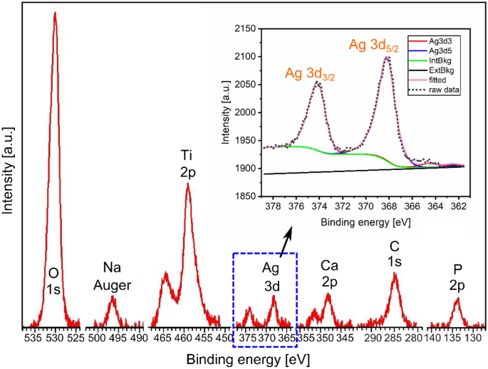
XPS spectrum presenting peaks (without carbon) obtained from the surface of MAO coating (spectrum of the Ag-3d level shown as inset).
| Ti [at.%] | O [at.%] | P [at.%] | Na [at.%] | Ca [at.%] | Ag [at.%] |
|---|---|---|---|---|---|
| 19.4 | 67.7 | 4.9 | 5.5 | 2.0 | 0.5 |
Table 1. Results of the quantitative analysis of the XPS spectra.
Based on the results presented above, a model is proposed describing the formation of the coating and the incorporation of Ag-NPs from the AgC2H3O2-containing electrolyte (Figure 5). Firstly, a large number of e– is generated due to the oxidation of titanium that yields to OH– ions arising from the decomposition of H2O in the cathode. The presence of OH–and Ti4+ produces Ti(OH)4 and then TiO2. The solubility of AgC2H3O2 in distilled water at 20°C is 10.2 g/l, thus, its amount of 0.002M should decompose according to the following reaction:
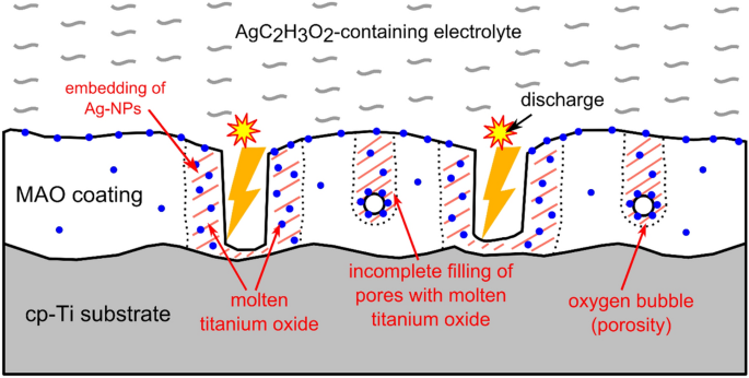
Scheme presenting the mechanism of incorporation of Ag-NPs in titanium oxide coating from AgC2H3O2 containing electrolyte.
The electric field applied between the anode and cathode forces the Ag+ ions, present in the electrolyte, towards the sites of the coating growth, and according to Clyne et al.25, this is the volume of the TiO2 coating formed near the centre of the discharge channel that melts during a single discharge event. In the meantime, Ag+ ions are prone to oxidation (in the vicinity of O2- ions) forming Ag2O oxide which, in turn, decomposes at temperatures exceeding 300°C into Ag atoms and O2 molecules26. The decomposition of Ag2O occurs due to a rapid rise in temperature in the discharge area up to even 12,000 K (estimated by optical spectroscopy) and a strong temperature gradient associated with it25. As a result of the mixing of Ag decomposed from AgC2H3O2 delivered to the discharge vicinity and molten TiO2, Ag embeds into the growing TiO2-based coating. Mosquera et al.22 showed that Ag does not dissolve in TiO2, but it is pushed away, forming Ag-NPs and this explains the presence of the Ag-NPs in the areas near the cavities, substantially, as well as near the upper surface of the produced coating. In addition, it enables the production of the Ag-NPs having a much smaller size compared with the conventional Ag-NPs provided by manufacturers (typically several tens of nm).
Conclusions
The application of high-resolution electron microscopy for investigation of MAO coatings prepared on the surface of cp-Ti with AgC2H3O2-containing electrolyte helped to describe its microstructure in detail and henceforth to prove that:
- The application of electrolytes containing Na2HPO4 and AgC2H3O2 promoted the formation of a porous amorphous-crystalline mixed titanium oxide coating with small metallic Ag-NPs (sized < 10nm) embedded within the coating.
- The density of the Ag-NPs was found to be much higher in the vicinity of the micro-pores and craters; moreover, some of the NPs are even protruding from the upper surface of the coating.
- The proposed mechanism of incorporation of Ag-NPs from the AgC2H3O2 into the MAO-produced coating comes from the decomposition of the AgC2H3O2 in the electrolyte, delivery of Ag+ ions into the discharge site after application of electric field, and subsequent precipitation of the NPs during the growth of the coating.
In summary, this work revealed the mechanism of MAO coating formation when AgC2H3O2-containing electrolytes were used intended for future biomedical applications i.e. to cover the titanium-based implants with antibacterial coating. The in-situ formation of Ag-NPs close to the surface and porosity of the coating explains their high antibacterial effect, because in this way the Ag-NPs may directly influence the DNA of the bacteria attached to the coating. The use of AgC2H3O2 in MAO is highly competitive with the addition of Ag-NPs supplied since it is less costly and more effective in terms of antibacterial effect without jeopardising the biocompatibility.
READ MORE:
Focus on Smart Coatings: Thin films and nanostructures by MOCVD
Data availability
The datasets used and/or analysed during the current study is available from the corresponding author on reasonable request.
References
-
Camps-Font, O., Figueiredo, R., Valmaseda-Castellón, E. & Gay-Escoda, C. Postoperative infections after dental implant placement: Prevalence, clinical features and treatment. Implant Dent. 24(6), 713–719 (2015).
-
Matos, A. et al. Three-species biofilm model onto plasma-treated titanium implant surface. Colloid. Surf. B 152, 354–366 (2017).
-
Chen, W. et al. In vitro anti-bacterial and biological properties of magnetron co-sputtered silver-containing hydroxyapatite coating. Biomaterials 27, 5512–5517 (2006).
-
Devrim Secinti, K., Özalp, H., Attar, A. & Sargon, M. Nanoparticle silver ion coatings inhibit biofilm formation on titanium implants. J. Clin. Neurosci. 18, 391–395 (2011).
-
Ferraris, S. & Spriano, S. Antibacterial titanium surfaces for medical implants. Mater. Sci. Eng. C 61, 965–978 (2016).
-
Thukkaram, M. et al. Antibacterial activity of a porous silver doped TiO2 coating on titanium substrates synthesized by plasma electrolytic oxidation. Appl. Surf. Sci. 500, 144235 (2020).
-
He, X., Zhang, X., Wang, X. & Qin, L. Review of antibacterial activity of titanium-based implants’ surfaces fabricated by micro-arc oxidation. Coatings 7(3), 45 (2017).
-
Fattah-alhosseini, A., Molaei, M., Attarzadeh, N., Babaei, K. & Attarzadeh, F. On the enhanced antibacterial activity of plasma electrolytic oxidation (PEO) coatings that incorporate particles: A review. Ceram. Int. 46, 20587–20607 (2020).
-
Hardes, J. et al. Lack of toxicological side-effects in silver-coated megaprostheses in humans. Biomaterials 28, 2869–2875 (2007).
-
Roy, M., Fielding, G., Beyenal, H., Bandyopadhyay, A. & Bose, S. Mechanical, in vitro antimicrobial, and biological properties of plasma-sprayed silver-doped hydroxyapatite coating. ACS Appl. Mater. Interface 4, 1341–1349 (2012).
-
Aydogan, D. et al. Optimisation of micro-arc oxidation electrolyte for fabrication of antibacterial coating on titanium. Mater. Techn. 33, 119–126 (2017).
-
Aydogan, D. et al. Surface modification of Ti6Al4V by micro-arc oxidation in AgC2H3O2-containing electrolyte. Surf. Innov. 6, 277–285 (2018).
-
Pesode, P. & Barve, S. Recent advances on the antibacterial coating on titanium implant by micro-Arc oxidation process. Mater. Today-Proc. 47(16), 5652–5662 (2021).
-
Bolli, E. et al. Hydroxyapatite functionalized calcium carbonate composites with Ag nanoparticles: An integrated characterization study. Nanomaterials 11, 2263 (2021).
-
Aspromonte, S., Mizrahi, M., Schneeberger, F., Ramallo López, J. & Boix, A. Study of the nature and location of silver in Ag-exchanged mordenite catalysts. characterization by spectroscopic techniques. J. Phys. Chem. C 117, 25433–25442 (2013).
-
Kumar, P. et al. Study of tunable plasmonic, photoluminscence, and nonlinear optical behavior of ag nanoclusters embedded in a glass matrix for multifunctional applications. Phys. Status Solidi A 216, 1800768 (2019).
-
Kumar, P. et al. Plasmonic Au nanoparticles embedded in glass: Study of TOF-SIMS, XPS and its enhanced antimicrobial activities. J. Alloy Compd. 909, 164789 (2022).
-
Prakash, J. et al. Synthesis, characterization and multifunctional properties of plasmonic Ag-TiO2 nanocomposites. Nanotechnology 27, 355707 (2016).
-
Kumar, P. et al. Plasmonic and nonlinear optical behavior of nanostructures in glass matrix for photonics application. Mater. Res. Bull. 125, 110799 (2020).
-
Maj, Ł et al. Titania coating formation on hydrostatically extruded pure titanium by micro-arc oxidation method. J. Mater. Sci. Techn. 111, 224–235 (2022).
-
Vincent-Crist, B. Handbook of Monochromatic XPS Spectra 1st edn. (Wiley, 2000).
-
Mosquera, A., Albella, J., Navarro, V. & Bhattacharyya, D. Effect of silver on the phase transition and wettability of titanium oxide films. Sci. Rep. 6, 32171 (2016).
-
Hofmeister, H., Tan, G. & Dubiel, M. Shape and internal structure of silver nanoparticles embedded in glass. J. Mater. Res. 20(6), 1551–1562 (2005).
-
Wang, J. et al. Silver-nanoparticles-modified biomaterial surface resistant to staphylococcus: New insight into the antimicrobial action of silver. Sci. Rep. 6, 32699 (2016).
-
Clyne, T. & Troughton, S. A review of recent work on discharge characteristics during plasma electrolytic oxidation of various metals. Int. Mater. Rev. 64(3), 127–162 (2019).
-
Zhang, X. et al. PEO coating on Mg-Ag alloy: The incorporation and release of Ag species. J. Magnes. Alloys 2022, 1–14 (2022).
Acknowledgements
This research was funded by the National Science Centre of Poland, grant number UMO-2020/39/D/ST8/01783. Authors also thank the support of VEKOP-2.3.3-15-2016-00002 of the European Structural and Investment Funds. This paper was supported by the János Bolyai Research Scholarship (Z. Fogarassy) of the Hungarian Academy of Sciences.
Ethics declarations
Competing interests
The authors declare no competing interests.
Additional information
Publisher’s note
Springer Nature remains neutral with regard to jurisdictional claims in published maps and institutional affiliations.
Rights and permissions
Open Access This article is licensed under a Creative Commons Attribution 4.0 International License, which permits use, sharing, adaptation, distribution and reproduction in any medium or format, as long as you give appropriate credit to the original author(s) and the source, provide a link to the Creative Commons licence, and indicate if changes were made. The images or other third party material in this article are included in the article’s Creative Commons licence, unless indicated otherwise in a credit line to the material. If material is not included in the article’s Creative Commons licence and your intended use is not permitted by statutory regulation or exceeds the permitted use, you will need to obtain permission directly from the copyright holder. To view a copy of this licence, visit http://creativecommons.org/licenses/by/4.0/.
Citation: Maj, Ł., Fogarassy, Z., Wojtas, D. et al. In-situ formation of Ag nanoparticles in the MAO coating during the processing of cp-Ti. Sci Rep 13, 3230 (2023). https://doi.org/10.1038/s41598-023-29999-7